Lab note
Lab Note #006 — Bass Manager Rev A: First Power-Up
I've started bringing up the first Bass Manager Rev A board. This is my adjustable analog crossover project for stereo speakers and subwoofers. The filters are analog, while a microcontroller and AD5206 digital potentiometers are supposed to handle the adjustments.
This is still the first hardware revision, so I'm working through the basics before I try to run audio through it.
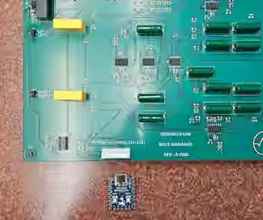
The resistor mix-up
One of the parts orders wasn't quite right. The 26.4 kΩ, 0.1% resistors came in 0603 packages, but I laid out their footprints for 0805.
The resistance is right. The package isn't.
We looked at whether the smaller parts could be hand-fitted across the larger pads for prototype testing. There's enough room to make a connection if it's done carefully, but that's a workaround for the bench, not how I'd want to assemble the next boards. The proper 0805 parts are still the sensible fix.
At least that mistake doesn't require changing the PCB.
The fuse
The bigger problem was at the power input.
I had about 12 V going into the board but only around 0.5 V past F1. The fuse path was showing unusually high resistance. The fuse I'd selected clearly wasn't working out for this circuit, and the converter's input/startup requirements need another look before I choose its replacement.
For a very brief diagnostic check, I temporarily bridged F1 with a solder blob. That let me isolate the issue and check whether the downstream supplies would come up.
Don't take that as advice to bypass a fuse. It removes the circuit's overcurrent protection. It's not a repair, and it is not safe or acceptable for normal operation.
The blob was sooo temporary — strictly an isolated bench check, not a way to run the board. A correctly selected fuse needs to be installed before continued testing.
First voltage checks
With the input problem isolated, I checked the rails:
| Rail | Measured |
|---|---|
| Positive analog supply | +12.2 V |
| Negative analog supply | −12.2 V |
| Positive low-voltage rail | +2.5 V |
| Negative low-voltage rail | −2.5 V |
Those are the voltages I was trying to get.
It's a useful first result, but it only tells me the power section can produce the expected rails. It doesn't tell me whether the analog filters are working yet.
Next up
I still need to sort out the fuse properly, finish the RP2040 controller connection, and initialize the AD5206s. Then I can feed the board a sine wave and actually measure what the crossover is doing.
Frequency response, channel matching, noise, distortion, and any noises or clicks when changing settings are all still untested.
For now, the board is assembled, the rails have been measured, and I've got a short list of things to fix before moving on.